Saturday, November 12, 2011

Oozing Black Crud

Close Up Of Test #1
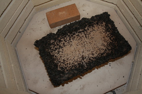
So, what really happened? This is a close up of the side of the test block. I originally thought, as I posted, that the seeds had popped. Nope. It looks like as they got to the temp where the oil started to plasticize and char. Then it began to expand and ooze out of the pores and cracks. Obviously it did not all ooze out so it broke the clay apart.

The black material at this point is dry, crunchy, and porous. It's almost like carbon foam. It's got no strength at all. It crumbles with a very small amount of pressure. So it doesn't serve to really hold the clay together at all either.

The whole thing looks a little like a chocolate cake with some funky black frosting. My daughter, the art major, said I could put it in a gallery. Maybe I can recover some costs. I can make five more of these tomorrow ...

It's a bust!

Test #1  Yeah, it's a bust. So I ramped it to 300 F. It soaked for another 2 hours. Did the mirror test with the kiln lid cracked about 20 minutes from the end of the soak. (You hold a mirror next to the opening to see if you get any vapor condensing on the mirror.) Good to go.

I went about my business chasing down some screwed up wiring in the house. About 45 minutes later I start to smell the seeds burning. Okay, that's about right I'm thinking. Checked it out.

Temp is at 554 F. Smoke is oozing out the crack between the lid and the kiln body. I got my welding gloves, opened the door to what you see in that picture. Hmmm ...

At first I thought I didn't let it soak long enough. I thought the big seeds were popping like they did in the toaster oven test. So I shut it down to let it cool. I was going to just let it soak at 300 F longer, write off the edges, and see what I could save.

Once the smoke cleared I noticed the large number of  what looked like popped seeds. The larger seeds in the mix are not that numerous. This had to be the millet. At this point I am sure the seeds near the surface like this are dry too. I mean c'mon, they HAVE to be dry. So what's happening?

A guy at iforgeiron.com who goes by Frosty, mentioned he thought millet had a relatively high oil content. Seeds in general have a good bit of oil as we know. So, what I think is happening is that as the oil is vaporizing and possibly burning, it's acting just like water vapor and causing the seed to expand. It would take a lot more testing to prove this out. I'm not going to do that. So, that's my story and I'm sticking to it.

Anyway, seeds as a burn out filler for a refractory brick are a no-go. Well ... now we know.

So for the next rounds of testing, I will drop the seeds and replace them with perlite. As I mentioned, perlite and "fireclay" are a reported to work just fine. The mixes I've seen don't go as hot as I'd like. I think that's got more to do with the clay than the perlite.

Firing Sample #1

Firing the first sample today. It was dry. I cut it in half with a back saw. It cracked straight through about half way into the cut. The center is totally dry. The other two samples had the same resonance to them when I tapped them. So I am sure they are all equally dry.

Firing program

Ramp at 150 F / hr to 300 F
Hold for 2 hours
Ramp at 1000 F / Hr to 2300 F* - 2300 F is about Cone 9
Hold for 2 hours

*Getting 1000 F / hr past about 1500 with this kiln is impossible. I'll be lucky to get 300.

I'm also going to have to monitor the breaker box. This is the first high fire cycle I've done at this house. I'm using a 10 GA copper cable that is tapped directly into a 30 A breaker. Should be OK. The max draw on the kiln is 1800 watts. That's like running two hair dryers at full heat or every light bulb in the house.

Well, we should have burning seeds before too long!

Dry time note - I think we ended up with ~50 - 60 hours dry time. The first 25% was at 160 F the rest was at 190 F. Starting at 190 F would have been the better way to go.


Wednesday, November 9, 2011

Cone 11 ?!

Looks like EPK vitrifies at Cone 11. My kiln might get there. Cone is a function of temp and time. To a point, you can get a higher cone at a lower temp. I've gone 1 - 2 cones higher in the past by letting it soak longer.

For the bisque, I should be able to go to cone 9 with a 2 hours soak. We'll see Saturday I guess

Pop Corn!

Did some testing on the seeds. Trying to figure out how hot I should go for the next hold cycle to drive off the remaining water. Here's what I got.

300 for an hour - all the seeds brown a little, no real smell
350 - almost immediately the cracked corn pops, everything else browns pretty dark, smells toasted
400 - some of the other seeds in the mix pop like the pop corn did, everything else gets a lot darker, some of the loose hulls start to char
450 - some more seeds pop, everything starts to char

Note: The millet did not pop at all and it was the last to char badly.

So the answer is 300 F for the max hold temp to drive off the water. If anything in the mix pops, I'm screwed, the whole thing will start to crumble from the inside out.

Tuesday, November 8, 2011

'Nother induction furnace link.

Hildstrom Engineering ... interesting induction furnace project. Someday ... an induction heater would be handy to have around. It's a lot less BS for probably 80% of what a guy needs. If you could get one built big enough to melt 100 lbs of bronze, you'd have a really nifty foundry. In a DIY setting I am afraid that would probably tax the available power to the house.

"Hello, PG&E, yes I need a service upgrade. What for? Uh ... well ... I have this really big medical marijuana green house I'm building ... what? ... oh yeah totally for personal use. I've got arthritis real bad ... oh ... prescription? Let me find that and get back to ya .... yeah, thanks ... you too ..."

Maybe 25 lbs ...

Approaching dry

"Older Slab"
"Newer Slab"
Sixth day of kiln drying of my 1st test of a home brew refractory using bird seed as the organic burnout filler to create gaps for insulation.
Started the kiln today. One benefit of being home sick, I guess, is that I can run these whilst I sit on the couch. Another day at 190 F.

Making some progress. You can sorta see the color differences in these two shots. These are both shot with the flash in the shade to minimize color variance from the sun. The older slab is beginning to get and stay white. Well whiter. The mold has either gone away or bleached out or something.

The newer slabs are still, by comparison much darker. Mold is still present. In fact when I turned them this morning there was mold on the shelves. Who knew mold was happy at 190 F? There's something to think about when you are looking at toasting that last piece of bread that may have been around a day too long ... ewww.

You can see where I'm losing the corners. They are either flaking off or I keep hitting them on the sides of the kiln. Not critical. If these make it through firing, I can grout that with the Sairset and some silica sand.

Not real exciting stuff right now, but this is what I get for too much water in the mix.

You'll burn your eye's out kid

Check this out - An old Popular Science Article on making a small arc furnace. I think I've discovered my problem. All this time I've been mucking around in my home laboratory in jeans and a t-shirt. Apparently a jacket and a bow tie are actually  the fashionable choice. Who knew?

Link to the page where I found it. 

Monday, November 7, 2011

Interesting Paper From Purdue


ATLAS FOUNDRY COMPANY, INC.
Marion, Indiana
July 1996
POLLUTION PREVENTION TECHNOLOGY IMPLEMENTATION REPORT

INTRODUCTION

Atlas Foundry Company and the Indiana Pollution Prevention and Safe Materials Institute (IPPI) have worked together for several years on projects involving routine Community-Right-To-Know and hazardous-chemical-use reporting to the EPA. The company was, thereby, aware that IPPI collaborates with companies throughout the state, including other foundries, to reduce hazardous chemical use and/or emissions. Atlas Foundry made plans to convert from a cupola melting furnace to an electric induction furnace process and, knowing of IPPI's pollution prevention and pollutant emissions reduction work, contacted IPPI with an invitation to review this change of process with regard to hazardous chemical emissions, solid waste reduction and economics.

COMPANY BACKGROUND

Atlas Foundry Company, Inc., which manufactures gray iron castings, is a family-owned business, which was founded in 1893 and is located in Marion, Indiana. They produce a wide variety of castings, usually less than fifty (50) pounds in weight. The company employs 131 people and, in the past, produced in excess of 17,000 tons of iron each year, utilizing a 1940's-vintage cupola melting furnace capable of twelve (12) tons per hour, continuous.

MANUFACTURING PROCESS

Atlas' cupola furnace was typically charged and recharged with a combination of pig iron, steel scrap, iron manganese briquettes, coke, and gray iron waste from prior casting (gates, risers, unacceptable cast parts). The molten gray iron, thus produced, was transferred from the cupola via ladle to a forty (40)-ton storage furnace. From the storage furnace, molten gray iron is transported throughout the facility in small ladles and poured into various sand molds. After a casting has been poured, cooled, and separated from its sand mold, gates, runners, and risers are removed and the casting is placed on a conveyor and transported to a shotblasting area to be cleaned. Following cleaning, the casting is inspected and touched up, as required, to remove excesses at parting lines and so forth. Testing of the 'brinell' hardness level, related to the ultimate strength of material of the casting, determines its acceptance or its return for remelt. A significant quantity of gate and riser material (along with a small percentage of imperfect castings) provides a remelt factor of approximately 40% of the total cast material. Viewed from the contrasting perspective, 60% of the gray iron produced is in the form of product, and the balance is recycled as a natural part of the process.

ENVIRONMENTAL ISSUES

The foundry industry has historically been characterized by large quantities of emissions and waste residues. This has been the case for the primary processing/refining of raw ore as well as the secondary production of metals such as gray iron castings. In this secondary metallurgical process, the major air contaminants occur as metallic fumes, smoke, and dust. Significant amounts of landfill waste are also generated as expended sand, sludge, slag, baghouse dust, etc.

Cupola-type furnaces use coke as a fuel. Iron is melted by the burning of coke and flows down the cupola. As melting proceeds, new material is added at the top. Added flux combines with nonmetallic impurities in the iron to form slag, which is lighter than molten iron and separates. Both the molten iron and the slag are removed at the bottom of the cupola. Sand is used as a refractory lining in the cupola and must be dropped at the end of each day's cupola operation. This is not a reusable waste (cupola drop).

Complete conversion of carbon that is present in the coke (producing 100% carbon dioxide [CO2]) in cupola melting is undesirable. Highly efficient fuel burning would result in oxidation of the iron as it is melted and runs down through the cupola stack. Such oxidation is minimized by assuring the presence of carbon monoxide (CO). During the iron's descent, it is in direct contact with the offtake gas, which purposely is oxygen poor (about 11% CO content). This minimizes the oxidation of iron but results in less efficient use of the available energy from the coke and, also, in the release of copious amounts of CO gas emissions to the environment.

The cupola process inherently produces a significant amount of particulate emissions. A high energy scrubber unit had been part of the structure since 1987. Ninety-nine percent (99%) of the particulate generated was directed to this scrubber, of which 95% was removed from the final cupola stack emissions. The resulting scrubber sludge is a landfill waste.

Although the basic pig iron used in the process contains no lead, scrap iron used as a part of the process is generally thought to occasionally contain some small level of this element. When it is present, some portion of it invariably will become a part of the emissions scenario.

Gray iron, by design, contains an EPA-reportable, heavy metal ingredient--Manganese (Mn). In 1995, the gray iron manufacturing operation resulted in a reported release of almost 10,000 pounds of this material to landfills or in air emissions.

P2 PROJECT

Atlas Foundry Company established a project to replace the cupola furnace with two, four-metric-ton, batch-load, electric coreless induction furnaces. This type of furnace produces substantially lesser amounts of environmental pollutants. The electric induction furnaces are cylindrical or cup-shaped, refractory-lined vessels that are surrounded by electrical coils. A 2500 KW, 200-300 Hz, power module energizes the coils, producing a fluctuating electromagnetic field which heats the metal charge. Typically, they are kept closed-- except when charging, skimming, or removing the molten metal, which is accomplished by tilting the unit hydraulically.

These new furnaces are located in close proximity to the 40-ton holding furnace. A cold batch of material is loaded and full power applied. As melting proceeds, additional material is added until full charge is reached. When the complete charge is melted, the furnace is slagged, temperature and chemical composition are checked and adjusted, the furnace is slagged-off, its temperature is raised to 2750 degrees F, and the material is transferred to the holding furnace. A 25,000 cfm dust and fume collection hood system over the furnaces collects and filters out particulate and fume emissions. This type of furnace uses no coke, produces no CO emissions, and, therefore, achieves an immediate and significant pollutant reduction. Although some form of energy conversion must take place elsewhere to produce the electric power required, unlike the cupola, there is no purposeful production of CO rather than CO2 in power generation operations. The CO reduction at Atlas is truly a reduction--not a transfer. There is no cupola drop, at the end of each day, producing air emissions and related landfill waste. There is, however, the need to periodically dispose of spent furnace lining material. Slag production is greatly reduced because the basic charge is much cleaner. There is no cupola scrubber sludge to be disposed of at a landfill although a much lesser amount of dry baghouse dust does require disposal.

Reduction of the above wastes and related particulate emissions have a direct, positive effect in reducing the amount of manganese (Mn) released by the operations.

The incorporation of these furnaces will allow for easier, future expansion of the range of iron alloys produced. Some of these would conceivably contain chromium. On a "what-if" basis, these furnaces would provide the same percentage reduction in emissions of chromium as achieved on manganese when compared to cupola production.

POTENTIAL ENVIRONMENTAL AND COST BENEFITS

First and foremost, a recalculation of 1995 Form R data, using the latest available input for the cupola operation and comparing to the values for an electric induction furnace, yields a 53.2% reduction in releases of manganese, overall. Releases to the air are reduced more than 25% and landfill input is reduced by 59%.

The furnace related operations are only a portion of the total source of landfill wastes and air emissions at Atlas (or any other foundry), but, the other sources (such as shakeout to remove castings from the sand molds) did not change as a result of this project. Only the environmental emissions and wastes associated with this project are covered in the following summary:

Calculations based upon the comparison table reveal:

Furnace related pollutants have been reduced 99.5%.
Furnace related landfill waste has been reduced 92.1%.

A cost comparison made by Atlas Foundry indicates $49.98 - 43.08 = $6.90 per melted ton reduction in related operating costs. At the 1995 annual melt rate of 18,273 tons, the savings produced is $126,084 annually.

Various sources of economic assistance have been available, such as local economic revitalization capital investment tax abatement, a low cost economic incentive loan, and power usage discounts, which help to reduce the payback of approximately $1.25 million outlay to an acceptable level. Flux materials are added that combine with nonmetallic impurities to form slag which, being lighter (less dense) than the molten metal, separates from the metal.

(c) Purdue University Research Foundation, 1996

One more day ...

Started the kiln up at about 09:55. Leaving it set for 190. It had cooled down to 55. The lid is open about 2 inches to allow for air circulation. Last night when I stopped there was no sign of cracking on the oldest slab.

Sunday, November 6, 2011

Slabs have been in the kiln for about 14 - 15 hours yesterday and 11 hours today at 160. The one I cooked last week is still damp. I just ran the temp up to 190 F. It's 16:00 now. I'll shut it down at 21:00. That'll give it five hours with 30 degrees more temp.

190 is the limit. I got cracks at 200 in the first sample.

I haven't been feeling well this weekend, so no progress on anything else. Good race at Texas today. Nice to see Tony Stewart coming back.

Saturday, November 5, 2011

Moon Rocks

IMG_3798
Moon Rocks!
Fired my sample piece. This is what I got. The original shape was a mini furnace. It was just a little pizza oven looking thing.

IMG_3802
Next to the lens cap for some scale
Based on some comments I've gotten at iforgeiron.com, I'm 99% I got this too wet. It was wet like clay for pottery. As such, it was drying really slow. I an effort to speed that up  put in the oven at 200 degrees. It started to crack. I was hoping the cracks were just on the surface. Nope....

IMG_3818
Some of the bigger chunks
The next step was to take it to 500 degrees in the kiln to burn off the organics. Well that worked, but the cracking got worse. I touched it with my glove at that point and the surface caved in. Hmmm. I decided to keep going. It had been soaking at 500 for about an hour. It was totally black. The carbon from the burn off had saturated everything.

I decided to take it to a cone firing at that point. I reset the controller for I think cone 05 or 06. I wanted to at least get the organics burned off.

About an hour later it was at 900. I peeked in again. It had begun to collapsed. Most of the black had gone away. I think at that point I let it go for another few hundred degrees. It was at about 1100 - 1200 that I opened it up again and shut it down. While there was a lot of white, it had fallen apart at this point and there was a glowing red core in the middle of the pile. I could see through a hole in the pile. Looked very volcanic.

So now I am drying the slabs I made. I'm going to see if drying them at 160 degrees F will make a difference.

I think the seeds are a bust. Big holes in the matrix may not leaving enough clay to stabilize the structure during the burn off. This has got to be leading to concentrations of stress and then crack propagation. It was also suggested that the seeds may be expanding during the process and there's a thought that the high oil content may be creating too much hot gas too fast.


Two other things missing in my mix are a larger aggregate and a flux. The chunks from this run can be used as a grog. If the other slabs bite the dust, they can be grog too. The other option is to get some silica sand.

For my next trick, I am going to go to small batches with different mixes. All will be with way less water and some slake time. "Frosty" at iforgeiron.com made a whole bunch of suggestions about how to mix it.

I'm thinking this for trials:

  • Clay blend but with sawdust
  • Clay blend with flux and seeds
  • Clay, flux, and sawdust
  • Clay, flux, seeds
  • Clay, silica sand, sawdust
  • Clay, silica sand, seeds
  • Clay, silica sand, flux, sawdust
  • Clay, silica sand, flux, seeds
  • Clay, grog, sawdust
  • Clay, grog, seeds
  • Clay, grog, flux, sawdust
  • Clay, grog, flux, seeds
I have to research what to use for a flux. Fluxes are elements or compounds that cause other elements or compounds to flow, generally at lower temperatures. Some also drive off impurities. Soldering flux is what most of us are used to. 

An example is boron & silica. Pure silica will not melt until something near 3000 degrees F. Throw in a little boron and that drops to the 1300 deg. F range. I don't think boron is a true flux in this case as it sticks around.

I'm going to go 2 - 3 at a time so I learn something as I go and hopefully I can adjust and close on a successful formula faster. So ... time to break out the spreadheet and do some math. 

Oh ... I found perlite at Home Depot. So that's going to go in here someplace too. A reportedly successful castable mix is to use refractory mortar mixed with perlite. I have some Sairset mortat. So, I may try a small batch of that with perlite in the first run too. 


Meanwhile the slabs are in the kiln at 160 F for a couple more days I s'pect.

Monday, October 24, 2011

Watching Clay Dry ...

Not much to report, really. The slabs are drying. I did cook a sample in the kiln at 200 degrees F for 8 hours yesterday,  no major cracks. That's encouraging!

I did have the idea to make half the slabs with seed and half with saw dust to see which works better long term.

Best,
John

Sunday, October 23, 2011

Chile Forge

 Stumbled on these guys last night; Chile Forge. Not at all sure how long they've been around. The forge the size I'm building in their line is $795.00. That's probably about right. These look to be well thought out. There's a good bit of welding on them. I like the work holders.

Right out of the gate I'd be adding something for a door.

It looks like they've added interior protective shelves over the ITC-100 coated Kaowool (or similar ceramic fiber). Good approach. I would ask about what the shelves are made of. Should be a 40% + Aluminum Oxide content clay by what I know.

Even their big one shown here will not work for me as a melt furnace. One of my design criteria was that I had to have enough room to put two #6 crucibles in there. Remember I am going to try to melt iron or maybe steel. So a comercially made crucible is going be e must. I don't have an autoclave to fire A really high temp silicon carbide crucible in.

That said. If one was going to to small aluminum melts, something more like 5 lb. ladle would fit fine in there two burner model, probably.

Anyway, these look like great forges for the buck. We'll see how mine stacks up cost wise once I get done.

Friday, October 21, 2011

Great Burner Safety System Ilustrations

"Great" is relative. The bar is low.

Anyway check out this link.

I live in the lower Oakland hills. 20 years ago, about five miles to the north, there was a huge fire that wiped out 90% of several neighbor hoods. I don't want to be the guy to start the next fire. So, once I get the forge out of the experimental phase, it's getting a safety system.

The same company has a nice burner setup that is essentially a modification of a burner I think I posted earlier. It replaces the bell reducer or taper based flame holder with a lot of little holes in a much larger diameter "nozzle" for lack of a better term. They call it a burner head. Whatever.

If the firebrick works, I can use my mix to fabricate one like it.

Later,
-jd

Thursday, October 20, 2011

Need more combustibles

After looking at the clay mix and poking around some more on the 'net, I've decided I need more millet / sawdust, jute or maybe even sisal / hemp.

An article I found indicates that 28% sawdust by weight. I also gives a number I have not seen before called "apparent porosity". This is a quantification of what I was doing visually by comparing my mix to the the IFB (insulating fire brick) my kiln has in it. That article says the apparent porosity is about 70%. 

Apparent Porosity (%) = {(Soaked Wt - Dry Wt) ÷ (Soaked Wt - Suspended Wt)} x 100

A quick read on this is that it's determined by by sectioning a piece of material weighing it dry, soaking it in water, then weighing wet, then pulverizing it and putting into a suspension with water to a specified volume (which I am still looking for right now). So, basically it's the ratio of the water the sample retains divided by a theoretical max. One could then easily equate that to volume given water has a density of 1g / cc. See I DID remember something from my Jr. high metrics blitz and intro to physical science. 

Well, I don't have time to make samples and do destructive testing so I'm going to eye ball it. My clay / sawdust / millet mix looks to be no more than 25% porous right now. So I have to step it up a notch.

Yesterday I wrapped up the clay slabs so they would not dry anymore while I pondered this little problem. Tonight on the way home I'm going to see about getting some big bags of bird seed at the grocery store. How much though?

Well, the dry mix to wet mix volume went down by about 30% - 40%. So I have about 7 - 8 gallons of clay after it's mixed up. There's about 1.5 - 2 gallons of millet & saw dust in there now. So, I need about another 2 gallons worth of millet. I'll get more and do some additional math on this. 

Jute / Sawdust / Sisal / Hemp / Fiberglass?

Two concerns. One is cracking as it dries. The second is max durability during service. I think I'm screwed on the second one. It is what it is. I coud put in glass fibers, but they will just melt. But ... if I get some kind of organic fiber introduced into the wet mix, I can help the cracking while it dries. I think I can get stuff like this at the craft store. I've seen it used in plaster casting. The second benefit here might be that it provides pathways for the burn out gases to escape. 

Okay, that's all the rambling for now.

Sunday, October 16, 2011

Making some clay


Stared working on the panels for the forge. Started by getting the proportions right. After half an hour resurecting some algebra skills I came up this this:

EP Kaolin - 31.75 lbs
Aluminum Oxide - 13.25 lbs
Zirconium Silitcate - 5 lbs

I used the bathroom scale for the EPK. I then used a lab scale I have for the smaller weights. The 31.75 lbs of Kaolin filled almost an entire five gallon bucket. The bucket was then split into two buckets by sight. As the Aluminum Oxide & Zirconium Silicate were weighed out they were added to each bucket. Finally the millet and a little sawdust was added. I decided to add the sawdust to give it some strength while it's drying. Hopefully that will help prevent cracking to some extend. In all about 15 lbs of millet and about a pound of sawdust was added.

Adding the millet
Dry clay ingredients before mixing
Adding the sawdust

Drill with mixer


Clay after mixing with drill
Once the dry ingredients were divided and the sawdust and millet were added to the buckets, a drill with a mud mixer was used to blend the dry ingredients. Then water was added until the mix was thick, pliable, and most of the ingredients were combined.

Following that, the whole bucket was emptied onto the bench and the remaining un-mixed material was hand mixed until it was uniform. I am told this is called wedging. I'm pretty sure what I was doing had no resemblance to actual wedging. At any rate it was mixed.

Then I pressed the clay into the forms I had made the day before. I used some scrap wood to pull across the top of the form. With a slight side to side motion this eventually left a pretty smooth surface. Smooth is not as much the point as it being free of voids that would allow heat to escape.

After a few hours the backs were taken off to let them dry faster. I also added some clay to the backs and pulled them with the scrap wood again to fill in several voids that remained after I molded them in the first place.

Note that I tried to lift the backs off. No go. This just pulled more clay out of the surface. I then took to hitting the bottom sideways to shear it loose.

Now to let them dry. Hope they don't crack! Once they get pretty dry I think I'll put them in the kiln at 200 degrees for several hours to see if we can dry them faster.

I have enough EPK for more. I am going to need another five pounds of Aluminum Oxide and Zirconium Silicate.

Saturday, October 15, 2011

Shrinkage

Started building forms for the clay today. In sizing the forms, had to allow for shrinkage. I'm going to assume the EP Kaolin will be the dominant factor so I'm going to use Edgar's data on this. I put that into an Excel file to calculate it and it looks something like this:


Shrinkage Table for EP Kaolin by Edgar Minerals

Dry Fired - Cone 11 (1315 C)
Shrinkage 5.0% 11.8%


Formed 1 2.000 2.125 2.250 2.375 2.500 2.625

4.750 4.875 5.000 5.125 5.250 5.375


Dry 1 1.900 2.019 2.138 2.256 2.375 2.494

4.513 4.631 4.750 4.869 4.988 5.106


Fired 1 1.764 1.874 1.985 2.095 2.205 2.315

4.190 4.300 4.410 4.520 4.631 4.741


The units are inches. The entire table in excel is here.


Friday, October 14, 2011

"The Toaster Project" - New Book

I just ordered a book called "The Toaster Project". This guy decided to build a toaster from raw materials. It got some interesting reviews. Sounds like the dude ended of with toast, but not a very serviceable toaster. It also sounds like he took a pretty extreme approach. Not even the first toaster maker started with raw materials.

It also sounds like he tried to take a bunch of short cuts and failed to study what he was doing very much. For instance there are some pictures of him trying to smelt steel in, as best I could see, a small blast furnace made out of a clay pipe. As anyone looking at the subject knows, just making a serviceable furnace of any type is a big job.

So, I'm thinking maybe it's time for a challenge. I have a pretty remarkable collection of tools at this point. Can I build a working toaster using tools available to me with my budget and using nothing more than stock sheet, rod, tube, pellet, powder, liquid, and wire materials. Modern "raw" materials if you will.

Well, something to think about anyway. First, I need to get this furnace on line.

Wednesday, October 12, 2011

Recipe Update

Got the stuff at Leslie Ceramics. It was suggested to me to add in some Zirconium Silicate by a friend who is a ceramics guy. So I got 10 pounds of that as well.

Rethought the couscous and went with millet seed instead. It was like $1.50 / pound at Whole Foods Market. I think the millet will expand less as the clay is drying. It still has the consistently round quality of the couscous and will burn out just fine. I'm thinking about 25% by volume right now.

Hopefully will make some molds tonight and get one bottom panel formed up and drying as a test. I'm going to split each side into at least two sections to allow for expansion and mitigate repair problems down the road.

Sunday, October 9, 2011

Ward Burner


Ward Burner

http://wardburner.com/home.html

The prices look pretty good considering how much work this takes. Still, I like the challenge. I also like knowing how to fix it when it breaks and never having to worry about getting parts.

DIY Refractory Cement Formula Decision - Couscous

The science content here leaves a lot to be desired. Doing the best I can not to screw this up too much.

I've been stewing over what recipe to use for the insulating refractory panels that will replace the fire brick. After many hours spent reading and dredging up what I remember of chemistry I've come up with some conclusions:
  • The chemistry of how alumina (aluminum oxide) behaves when fired is a bit of a mystery even to those who know chemistry really well it seems.
  • Aluminum oxide absolutely raises the working temperature of the ceramic.
  • There is a clay called Kaolin that has somewhere from 28% - 40% aluminum oxide (alumina) in it that is used in most firebrick recipes and I think many "fire clay" recipes.
Here's the analysis for Lincoln 60 Fire clay

K2O - 2.00%
Al2O3 - 29.00%
SiO2 - 52.00%
Fe2O3 - 2.00%
LOI - 12.40%

Here's the analysis for EPK Kaolin

CaO - 0.18%
K2O - 0.33%
MgO - 0.10%
Na2O - 0.06%
TiO2 - 0.37%
Al2O3 - 37.36%
P2O5 - 0.24%
SiO2 - 45.73%
Fe2O3 - 0.79%
LOI - 13.91%

LOI = "Loss On Ignition" I assume these are organics or hydrocarbons with flash points well below the temperature needed for vitrification. Vitrification is generally used to describe the point at which some of the silicon oxide begins to melt.

The Lincoln 60 analysis very likely omits trace elements below 2%. So if you look at the big hitters here they are aluminum oxide and silicon oxide (silica). The organics are important as they likely provide some of the binding action when water is added. 

The aluminum oxide and the silicon oxide have an affinity for water. I haven't tried it yet, but it must have a role on creating the sticky consistency of the clay. We all know how granular sand tends to stick together when wet, the powdered silica has to be doing nearly the same thing. This affinity for water is called hydrogen bonding. It's a fairly weak bond. It can be broken with a little bit of heat of even just having an imbalance of water in one place as compared to another (air). The water will evaporate off the bond is so weak. 

This affinity for water gives the silica and the alumina the ability to stick together so you can mold or shape the mix. 

Oh, This is NOT cement.

Cement and mortar are based on a combination of calcium oxide reacting with carbon dioxide and other components like aluminum oxide being converted to hydrates like aluminum hydroxide. See this article.

As far as I can tell, this hydration process is not associated with the making of clay based refractories. 

Ok great, so what's the recipe going to be?
  • EPK - Kaolin
  • Aluminum Oxide (enough by weight to add 3% - 4% to the mix)
  • Couscous
The "normal" recipes use saw dust. The saw dust burns out of the ceramic leaving voids that create the insulating properties. The gap don't transmit energy well, and the sheer reduction of mass reduces the thermal conductivity of the ceramic. So why am I using couscous?

If you don't know couscous is a wheat based pasta that is round.

Here's why I think it will work:
  • It will burn out like sawdust.
  • It is more consistently sized and fairly large so the gaps should be bigger than with sawdust.
  • It's round. Round gaps don't have sharp corners that tend to promote crack propagation. So, the resulting part should be stronger. 
So, this week I will make a stop at Leslie Ceramics and Safeway! Maybe this week I'll get to fire some panels. 

Wish me luck!


Sunday, October 2, 2011

Hot steel!

Yay! We've got hot steel! This is a shot of a piece of 1 1/4 angle iron on it's 2nd or 3rd trip into the forge. The reheat from it becoming non-plastic to nice and red hot is a couple of minutes at this point. This is 30 - 45 minutes into the first firing.

Work on the forget today started out fitting the lid bricks. I made a 30 degree ramp out of some wafer wood to hold the bricks at the right angle on the tile saw. This tile saw does 90 & 45 degrees only. So I needed something to angle the bricks since the blade could not be set at 30 degrees. About 50 cuts later I had a roof on the forge.

At that point I used a grit edge 2 inch hole saw to bore the burner hole in the side of the forge. The bricks are not grouted in at this point. A piece of wood  was used to back up the brick so the hole saw could push through. Once the hole was bored a bar clamp was used to provide a temporary support for the burner. A vise grip clamp held the burner against the bar clamp. After all the propane was hooked up it was time to fire it up.

Lighting is was a pain in the ass. I used a long propane lighter. It kept going out when I put it in the forge. Either too much gas or something. Only once did I get a small blow out and singed a little bit of arm hair. I did not want to stick burning paper in there because I did not want hot burning paper flying out.

Got it lit. After a couple of flame outs I got the balance of fuel PSI and the opening in front of the forge close. It was darn close to a reduction flame. With two burners it will need a bigger opening. Some of the more successful furnaces I have seen have a chimney.

Temperatures - I've been concerned that the generic fire brick I used was going to be too conductive of heat. It's right on the the edge. The outside temps at peak ran from 80 degrees to 300 +/-. Nothing I could find was over 300. Ok ... so?

Lets put this in perspective. My ceramics kiln will be 1600 - 1700 degrees and the outside will be no more than 250 degrees. I don't have enough experience with this one to see what the outside temp will be as we approach 2000 degrees, but it's going to be a hell of a lot more than 300 degrees. Long term, the fire brick is not going to work. Further it may even vitrify. If so I'll have a pile of really hot glass on my hands.

Next is the question of how to come up with a decent refractory compound that I can get the materials for. There are many formulas. The trick is getting the materials. If getting the materials is too resource intensive then the castables that can be purchased are more cost effective. I would like to over come this because the castable mixes are not cheap. This forge would have cost me $200.00 in castable refractory.

The argument, which I agree with, is that the fuel cost savings make up for the investment many times over. My objective was to simply get a working box of bricks with fire inside at the lowest cost possible. Once I get the 2nd burner in there and working, mission accomplished.

So anyway ... it works and I managed to bend some steel.

Thanks to Teri and Hayley for standing by with the phone, ready to call 911! Fortunately, no problems. Knock on wood!

Oh, forgot to mention the steam. Due to the saw cutting several of the bricks had a good bit of water in them. They steamed off a good bit. I was getting a little concerned. Then I figure these have already been fired. The water got in there via open paths so the steam could follow that paths back out. Fortunately that worked out. 

Wednesday, September 28, 2011

Link to burner & forge build photo series

Here's my Flicker Forge Album

I'm adding captions to the photo's still. Hopefully these help folks who might be having a hard time envisioning getting from the shopping trip to Home Depot to a finished burner.

Monday, September 26, 2011

The magic is 27/64ths

So the magic on the adapter between the 1/8" pipe and the 3/4" pipe is the 27/64ths drill and the 3/4 inch pipe thread to 3/8 inch compression reducer.

  1. Remove the compression ring from the fitting
  2. Using cardboard or a couple small pieces of wood to pad the compression ring, clamp it into either a vice or some vice grip plyers or find some other way to hold it
  3. Cut a slot in the ring perpendicular to it's circumference using a hack saw or a coping saw, the slot can actually be wider than this
  4. Drill out the fitting with the 27/64ths bit
  5. Slip the split ring over the 1/8" pipe
  6. Apply some kind of grease to the compression ring in case it needs to be removed
  7. Slide the compression nut over one end of the pipe and the drilled out fitting over the other one
  8. Tighten it up
Now you can loosen it, adjust the position of the jet, and tighten is back up. 

Once it's up to about 10 foot pounds it centers nicely. When it's just snug, you can wiggle it around a good bit as if it was a ball joint with limited range. An improvement would be to use a counter sink to restore more of the taper removed by drilling. 

Cost wise, this might be a bit more expensive. The fitting is like $15.00. An iron 3/4" plug, a couple of taps, and a couple of screws is probably $5.00 less.  

Sunday, September 25, 2011

Now there are two

More FIRE!

Burner #2 running at 30 psi of propane
This morning it started raining so that pretty much put the damper on doing any work on the furnace box. After doing some work for a couple hours, I decided to go ahead and get burner number two going. As you can see here, it was a success.

Burners #1 & #2
There are a couple of differences worth noting. One, I used a coupler for liquid tight electrical conduit. Two, I used a 3/4 inch MIP to 3/8 inch compression reducer to hold the gas jet pipe. This was to improve on the DIY compression clamp I made out of the bored out hose barb.

The compression ring was cut with a hacksaw thus removing enough material to let it compress more and allowing it to be expanded of the threads of 1/8 inch brass pipe used for the jet tub. The fitting normally has a stop where a tube or pipe would be inserted to. This had to be removed and the inside diameter had to be increased for the pipe. I did this on my mini lathe. But I think it can be done with a 27/64ths drill. Anyway, This seem to be a good improvement over drilling out the cast iron plug and putting set screws in that.

The other difference is the shape of the air passages. I tried rounding the new ones. The size of the base rectangle is the same. I used a grinder to rough out the round shape. Then I filed it to round it out.

Interestingly enough, the jets ended up at about the same spot.It should be interesting to see if they behave the same when they are put in the forge.

Saturday, September 24, 2011

Little Boxes ...

So after the successful burner test I went back to the furnace part of the build. At this point it's pretty much a process of adding bricks, and cutting & welding steel. This is very much a design as I go process. It looks a lot different as it comes together than I could ever imagine it on paper.

I stopped today with the first two bricks of the lid in place. I'm not sure I'm happy with this. I think in the morning I'm going to make a 30 degree jig to hold the bricks on the tile saw better. Right now I'm just propping them up with another brick and eyeballing the alignment of the blade to a pencil line. Time consuming.

If the jig works, I'll feel better. That will allow me to cut some slivers to put in the gap between the lid bricks and the top course of the sides.

I could get really tricky and do some nifty half laps & stuff, but c'mon. The Sair-Set grout will probably do just fine.

More tomorrow.


We have fire, and a lot of it!

Burner running at 20 psi
First off a giant THANK YOU to everyone before me who has tinkered with these propane burners. I pretty much assembled this off others work and it goes. My only contribution is the compression clamp for the gas jet. I'm not even sure someone hasn't done that. I don't know of anyone, but, that's not saying it hasn't been done. 

With the .30 tip I'm able to have a stable flame up to 30 psi of propane. I'm happy with it. I'm not going to try the .35 right now.

At first I did not want to go higher with it clamped in the vice shooting out the front of the garage. Once it got a little darker and I could see the flame, I got a little more aggressive with the pressure. The adjusting clamp for the jet position is working nicely. I can get it snug, tune the flame with it running and then clamp it down after that.

There IS a sweet spot. I was able to go from rich to good to rich again. The sound of the flame is the give away. A big crackly flame is too rich. The quiet smooth flame is just about right.

Quiet is a relative term with this propane burner. It's not like a propane torch or a gas furnace or a propane BBQ. It has that unmistakeable gas torch sound. You can talk around it, but it's not silent at all.

DANGER - Gotta be careful! If I pull the jet too far back it flares at the air ports. At 5 psi it was a damn big flame! Fortunately it did not flare at 20 or higher.

Air slots after being opened up, rounded a bit,
having the edges filed off & sanded

This is good for now. I thought it was running a little rich until it got a little darker out and I could get the pictures. I did open up the slots more, rounded them, smoothed a few things out and that helped. It helped a lot. So, I want to see how it behaves in the forge before I go crazy with any more modifications. Having a little back pressure will create all kinds of new dynamics.

Staying on track - I've been looking at the recuperative forge designs like the Sandia Labs forge. Ya know what? I'm gonna wait until I get this one working before I start taking it up a notch. My experience tells me there is a lot to learn here. I should get to a stable base line at as little cost possible, and then go from there. 

I feel better proceeding with the furnace build now that I know I can make enough fire. I've got a lot of pictures. Hopefully I will be able to document this build in a very detailed way later. Right now I need to get this thing going.

Monday, September 19, 2011

When you're a jet ...


Here is what I think the gas jet is going to end up like.I've been trying to figure out a better way to do this since I drilled out the cast iron plugs. Getting a drill the same size as the pipe is almost impossible. If it were, the threads are rolled on a lot of these smaller pipes so the thread diameter ends up actually a little bigger than the pipe. Small problem when you are trying to get a tight fit around the body of the pipe. 
So I started thinking about the flare mentioned on one of the other burner sites. He slit a pipe nipple and screwed it into a coupling giving the inside of the the nipple a taper. So I thought that would be a good way to clamp the gas jet tube if I could find a combination of parts and slit whatever was screwing into a plug or reducer. So ... I dug out a 1/4 inch hose barb, drilled it out to 25/64ths, slit the remaining hollowed out "plug" in two directions and screwed it into a bushing. Put the gas jet pipe in there and cranked down the plug. Sure enough, it clamped down on the gas jet pipe. Solution! 

Well more on this later.

Friday, September 16, 2011

Burner Design

Well, I've Googled and Binged "propane burner", "propane forge burner", "Ron Reil", and all imaginable combinations of that and other things burner like. There are lot's of good ideas and burners out there. Then I ran into the "Oliver-Upwind" burner and build at http://www.backyardmetalcasting.com/oliverburner1.html Stupid simple. Seem to work great.

Check out this link for the Boorman build.

Conclusion - you can pretty much squirt gas into a tube with some kind of a flare at the end, light it and it'll go. There's some tweaking needed with where you might put holes on the tube and / or some kind of a bell near the gas jet to be sure. However it's pretty basic. I'm sure getting from this, to some super efficient burner requires a PhD and a $2 million research grant. But we are talking about introducing gas and air into a box that will be approaching 2000 degrees. Getting it to burn all the way is not a question. Getting it get past 1000 degrees, that's a different question.

One cool discovery is that MIG welding tips make great propane jets.

To test my theory I took apart a propane torch, used just the jet to squirt gas into a 3/8 inch pipe with a bell reducer on the end for a flame holder. Worked! Not great, but it worked. Heck I was holding everything by hand. So I'm going to use the basic Reil, Vulle, Cook burner with the Krucible reducer as a flame holder. I do like Larry Zoeller's design too. He uses a bored out pipe plug as a jet stalk holder. This allows the jet to be positioned in the pipe at various positions and tuned to the best spot for the given combinations of parts.


Sunday, September 11, 2011

Forge Build Day One


Base & First Course
First I needed to lay out the fire brick.This was to get some idea of the real size. I had sketched it before I got the bricks to get an approximation of the number of bricks.
It immediately became apparent that I needed to cut the brick so that I could stagger as many seams as possible. I split a few cross wise and a couple length wise. I used my tile saw. A dry cut skill saw blade could be used or you could use a brick set.
A brick set is a wide flat cold chisel. Once good shot with the hammer and most bricks snap pretty cleanly. If you are using a brick set I recommend that you use it on a flat hard surface. The idea is to keep the force of the cut as linear as possible. If the brick is stressed in other directions the crack will travel in the direction of the highest stress vectors. 
Tile Saw Used To Cut Bricks
Next it was time to cut some steel. I happen to have some 1 1/2 x 1 1/2 angle iron handy so I used that. I got it for a storage project in the garage. I got this at Granite Expo in Emeryville on Hollis. They have this great selection of all the basic steel shaped up to about 4 x 4 tube. They also have sheet, expanded metal, and a bunch of those cast shapes for fences if you like that stuff. I don't.
Angle Notched At Corners
Here is how I notched the angle iron after I cut it to length. I could have mitered it, but with the saw I have, that's not a good option. I'm doing the cutting with a carbide steel cutting saw in a standard 7 1/4 inch DeWalt circular saw. I've used it for probably 25 feet of cutting. So far so good. It is starting to get dull. I think I went too fast on the angle iron. Getting these saws too hot is the death of them. So going slow is key.
Base Frame After Welding
Base Course In Frame
After that I welded it all together. I had some plate handy so I used that as a support in the middle where the bricks will come together. At this point I fit the bricks back in the frame. They were tight so I had to trim a few more. I trimmed bricks I had not cut before to make for more straight seems. The bricks are slightly rounded as they come.
That's it for the day one. This all took about five hours from getting out the tools to getting cleaned up. Next will be adding some vertical corners and sizing up the lid.

Friday, September 2, 2011

Anvil

Every forge must have an anvil, here's mine.

Sometimes I wonder about fate and divine intervention. I decided I wanted to get back into blacksmithing. Right after this, several things "came" to me.

First we were on a short trip to Sacramento. We took the morning to go to the train museum in Old Town. There we went into one of the shops. They had a nice book on the blacksmithing craft. One of the best I have ever seen. I bought it.

Next I did a Yelp search for fire brick and found some good enough for a forge a few miles from home.

Finally I did a search on E-Bay for an anvil. One was there for $350.00 in Chico. Chico is close enough to drive. When you are trying to get hold of something that weighs 152 lbs., the shipping is really an issue. So for the cost of a tank of gas and $350.00 I got an anvil.

It's a nice anvil. Good ring. Classic shape.

It belonged to the sellers Dad. They both used it a little for this and that. It sounds like it's been in Northern California since this guy was a kid. So at least 40 years.

This weekend I will try to get the forge built and working. Maybe I'll be able to pound on some red hot steel!